

Time:2021-07-19 Views:187
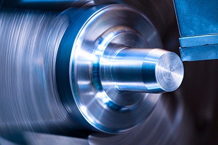
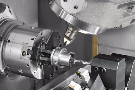
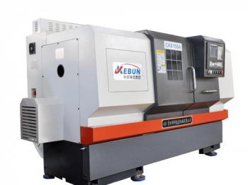
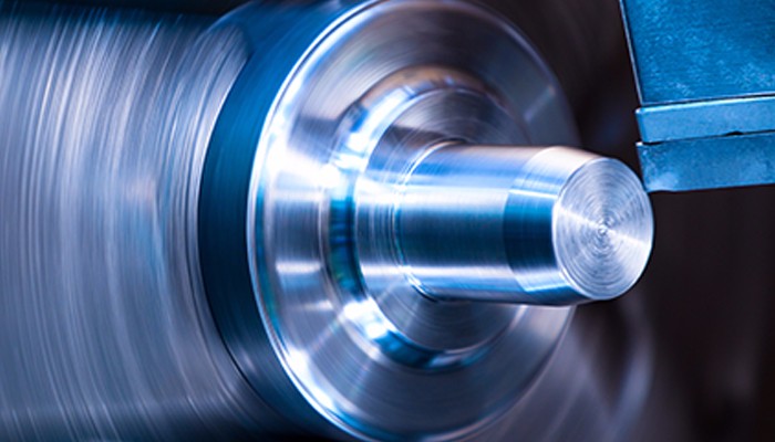
Threads are continuous protrusions and grooves with the same contour and specific tooth profile formed along a spiral line on the surface of a cylinder or cone. Threaded parts are widely used in various mechanical products. Mainly used for connecting parts, fasteners, transmission parts, measuring parts, etc. Thread machining on a CNC lathe is one of the most commonly used methods. Numerical control lathe thread processing has the advantages of high processing accuracy, good product uniformity, and wide processing range, and it plays an increasingly important role in mechanical processing.
Starting from the actual application, the faults and solutions that are prone to occur in the cutting process due to equipment, tools or operators when machining threads on CNC lathes are explained.
With the development of science and technology, CNC lathes are becoming more and more popular. Thread turning on CNC lathes is increasingly used in machining. CNC lathes have the advantages of high machining accuracy, good product identification, wide machining range, convenient debugging (especially for some special surface parts with high machining accuracy and difficulty in machining), etc., and they play an increasingly important role in machining. . Ordinary vehicles). Common faults and solutions for turning threads on CNC lathes are as follows:
1. Knife
1.1 Main reason
(1) The rake angle of the machine tool is too large, and the gap of the X-axis screw of the machine tool is too large;
(2) The turning tool is installed too high or too low;
(3) Insufficient clamping of the workpiece;
(4) Excessive tool wear;
(5) Too many cutting parameters.
1.2 Solution

(1) Reduce the rake angle of the turning tool, adjust the X-axis screw gap on the repair machine, compensate the X-axis screw gap, and have the automatic compensation function of the screw gap of the CNC lathe;
(2) The turning tool is installed too high or too low: If the turning tool is too high, the cutting edge of the turning tool will keep the workpiece at a certain depth, increase friction, and even cause the workpiece to bend, causing the tool phenomenon; if the turning tool is too low, the chip will not be chipped. When the E is unloading, the direction of the radial force of the turning tool is the center of the workpiece, and the gap between the horizontal screw and the nut is too large, which causes the depth of the tool to continuously and automatically deepen, so that the workpiece is lifted and the tool appears. At this time, the height of the turning tool should be adjusted in time to make the tip of the turning tool equal to the axis of the workpiece (the tip of the tailstock can be used for tool setting). In rough turning and semi-finishing turning, the position of the tool tip is about 1% d higher than the center of the workpiece (d represents the diameter of the workpiece to be processed).
(3) The workpiece is not firmly clamped: the rigidity of the workpiece itself cannot withstand the cutting force during turning, resulting in excessive deflection, which changes the center height of the turning tool and the workpiece (the workpiece is raised), resulting in sudden cutting depth Increases and emergencies. a knife. The workpiece should be clamped firmly at this time, and the top of the tailstock can be used to increase the rigidity of the workpiece. Sex.
(4) Excessive wear of the turning tool: The cutting force increases, the top of the workpiece is bent, and the tool appears. At this time, the turning tool should be sharpened.
(5) Cutting parameters (mainly reverse feed and cutting speed) are too large: Choose reasonable cutting parameters according to the size of the workpiece 5 lead and the rigidity of the workpiece.
2. The second step. Irregular deduction
2.1 Failure phenomenon
When the screw rotates, the workpiece does not rotate a whole number.
2.2 Main reasons
The synchronous transmission belt of the spindle encoder of the machine tool is worn, and the actual synchronous speed of the spindle cannot be detected; the input host programming error; the X-axis or Y-axis screw is worn.
2.3 Solution
(1) Spindle encoder timing belt wear: Since the movement relationship between the spindle and the turning tool is controlled by the command issued by the machine tool host information processing center during threading, the spindle speed is constant during threading. The X or Y axis can adjust the moving speed according to the size of the workpiece lead and the spindle speed. Therefore, the center must detect the actual speed of the spindle synchronization in order to issue the correct command to control the correct movement of the X or Y axis. If the system cannot detect the actual speed of the spindle, it will give different instructions to X or Y during actual turning. The distance the tool moves when the spindle rotates is not a guide, and the thread will be screwed in during the second turning. In this case, we must repair the machine tool and replace the main shaft timing belt.
2) Input programming error: in order to prevent
Related News
Related Products
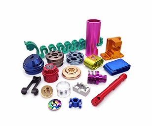
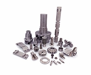
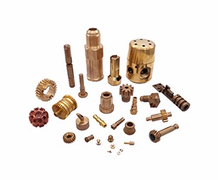
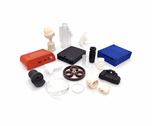
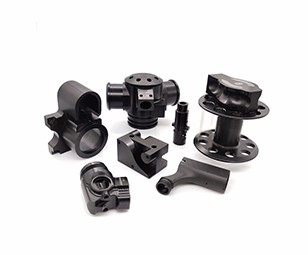
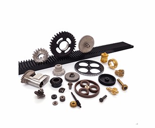
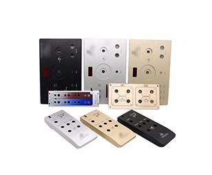
Aluminum(Anodized) / Aluminum(Raw finish) / Brass / Plastic / Titanium / CNC Machining Case /
Our Work

Process
News
E-mail:dennis@7-swords.com


 Inquiry


