

Time:2021-06-07 Views:176
In CNC machine tools, many functions are controlled by a programmable logic controller (PLC, programmable controller for short). This unit mainly introduces the application of PLC in CNC machine tools. This allows readers who are ready to engage in this work to have a basic understanding of the control objects of the CNC machine tool PLC, the form of the CNC PLC, and the function and working principle of the commonly used input/output components of the CNC machine tool.
Control object of CNC machine tool PLC
1. Classification of the control part of CNC machine tools
The control of a CNC machine tool consists of two parts: one part is the position control of the coordinate axis movement, and the other part is the sequence control of the CNC machine tool processing. When discussing the relationship between PLC, CNC and various mechanical parts of the machine tool, machine tool auxiliary equipment, and power lines, CNC machine tools are often divided into two parts: "NC side" and "MT side" (ie, machine tool side). "NC side" includes the hardware and software of the CNC system and the external equipment connected to the CNC system. "MT side" includes the mechanical parts of the machine tool and its hydraulic, pneumatic, cooling, lubricating, chip removal and other devices, the machine operation panel, the relay circuit, and the heavy current circuit of the locomotive. PLC is located between CNC and MT, and processes the input and output signals on the NC side and MT side. The final object of sequence control on the MT side is very different depending on the type, structure, and auxiliary equipment of the CNC machine tool. The more complex the CNC machine tool mechanism and the more auxiliary devices, the more final controlled objects. Generally speaking, the number of final controlled objects and the complexity of the sequence control program from low to high are CNC lathe, CNC milling machine, machining center, FMC, FMS.
(2) PLC In electrical control, PLC has m input/output (I/O points, as shown in Figure 1.1 b) above.
(3) The PLC is in the electrical control cabinet, and the input/output interface is on the side of the machine tool, as shown in Figure 1.1 c) above. This configuration method greatly reduces the number of cables connecting the CNC and the machine tool. The following figure 1.2 shows the schematic diagram of the input/output signal of the CNC machine tool PC.
3. Input/output signals of CNC machine tools
(1) Machine tool operation panel control.
Send the control signal on the operation panel directly to the interface signal area of the numerical control system to control the operation of the numerical control system, including M, S, T functions.
1) S function processing.
The spindle speed can be directly specified by S two-digit code or four-digit code. In the PLC, it is easy to directly specify the speed with a four-digit code. For example, the highest and lowest speeds of a CNC machine tool spindle are 3150r/min and 20r/min respectively. CNC sends a four-digit code of S to PLC, converts the decimal number to binary number and sends it to the limiter. When S is greater than 3150, The limit S is 3150; when the S code is less than 20, the limit S is 20. This value is sent to a digital/analog (D/A) converter and converted into a corresponding output voltage of 20~3150r/min as a speed command to control the speed of the machine tool spindle.
2) T function processing.
CNC machine tools can manage the tool magazine through PIC for automatic tool exchange. The content of the processed information includes the tool selection method of the tool magazine, the cumulative use times of the tool, the remaining life of the tool and the number of tool sharpening, etc.
3) M function processing.
The M function is an auxiliary function. According to different M codes, it can control the forward, reverse and stop of the spindle, the gear shift of the spindle gear box, the gear shift of the spindle gear box, the exact stop of the spindle, and the opening and closing of the cutting fluid. The clamping and releasing of the chuck and the taking and returning of the tool by the tool change manipulator.
(2) The control of the external switch signal of the machine tool. Send the control switch signal of the machine tool to the PLC, and output it to the control object after logical operation. These control switches include buttons, travel switches, proximity switches, pressure switches and temperature control switches.
(3) Output signal control. The signal output by PIC is controlled by relays, contactors or hydraulic and pneumatic solenoid valves to control the tool magazine, manipulator and rotary table, in addition to the control of cooling, lubrication and oil pump motors.
(4) Servo control. Control the enable signal of the machine tool spindle, servo feed and tool magazine drive to meet the conditions of the servo drive.
(5) Alarm processing control. When a fault occurs, the PLC collects the fault signals of the strong current cabinet, the machine tool side and the servo drive device, sets the corresponding alarm flag in the alarm flag area, and the CNC system displays the alarm number and alarm text to facilitate the diagnosis of the fault.
Related News
Related Products
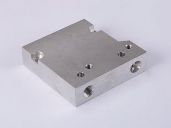
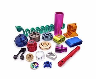
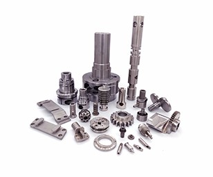
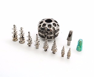
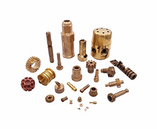
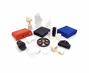
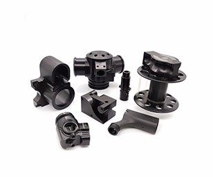
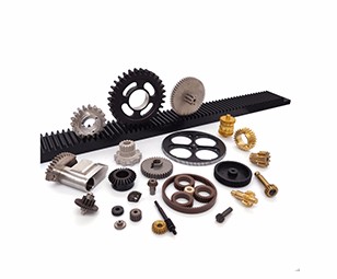
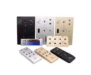
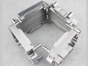
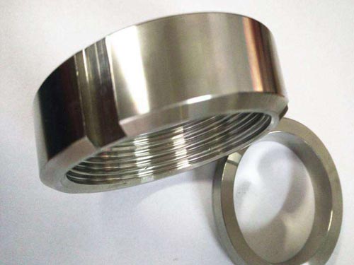
Aluminum(Anodized) / Aluminum(Raw finish) / Brass / Plastic / Titanium / CNC Machining Case /
Our Work

Process
News
E-mail:dennis@7-swords.com


 Inquiry


