

Time:2021-08-06 Views:147
Abstract: When using CNC lathes to process parts, firstly perform the operation of returning to the reference point to establish the machine tool coordinate system; then operate the tool, establish the workpiece coordinate system, and finally compile the part program and process it. The accuracy of tool setting directly affects the subsequent processing. In practical applications, there are three trial cutting methods for knife setting. This article mainly introduces these three types of tool setting methods.
Keywords: CNC lathe, machine tool coordinate system, workpiece coordinate system, tool trial cutting method
text:
When machining a part on a CNC lathe, it is usually turned on and reset to zero, then the part blank and the tool are installed, the tool is operated, the workpiece coordinate system is established, and finally the program is programmed and automatically processed. The correct operation of the tool directly affects the subsequent processing. If the tool fails, it will have a slight impact on the machining accuracy of the parts, and a serious machine tool accident. Therefore, as a CNC lathe operator, you must first master the tool setting method of the machine tool and the establishment of the workpiece coordinate system.
There are two tool setting methods for CNC lathes: trial cutting method and external tool setting instrument. Ordinary schools do not have this kind of equipment, so the knife adopts a trial cut method. According to actual needs, the trial cutting method can adopt three tool forms. This article takes the Huazhong CNC HNC-21/T system as an example, expounds the establishment of three tool setting forms and the workpiece coordinate system.
A pair of knives
The basic principle of T-pair is that for each tool, we assume that the tool tip moves to the center of the right end of the workpiece, record the position of the machine command X and Z at this time, and enter them into the tool X and Z offset in the tool offset table. shift. Subsequently, when the CNC system executes the program instruction, the offset value of the tool will be added to the X and Z coordinates of the instruction to ensure that the reached position is correct. The specific operations are as follows:
(1) Turn on the machine tool, release the "emergency stop" button, press the "zero" key, and then press the "+X" and "+Z" keys to return to the reference point.
(2) Press "Spindle forward rotation" to start the spindle, press "Manual" to move the tool to the appropriate position, then press "-Z" to manually rotate the outer circle, and finally press "+Z" to retract the tool in the Z direction, as shown in Figure 1 Shown.
(3) Stop the spindle according to "Spindle stop", and then measure the diameter of the cutting part. The diameter is 69.934. According to "F4 (MDI)" and "F2 (tool deviation table)", move the light bar to the cutting diameter of tool No. 1, return to the car, enter 69.934, return to the car, and automatically calculate the X offset of tool No. 1 ,As shown in Figure 3.
Figure 1, Figure 2
(4) Move the tool to a suitable position, press "Spindle Forward" to start the spindle, press "Manual", then press "-X" to manually rotate the end face, and finally press "+X" to retract the tool in the X direction, as shown in Figure 2. Shown.
(5) Stop the spindle according to "Spindle stop", move the light bar to the trial cutting length of tool No. 1, return, enter 0, and then return, the Z offset of tool No. 1 will be automatically calculated, as shown in Figure 3.
The whole knife process of No. 2 knife is similar to that of No. 1 knife, but the end face cannot be cut. details as follows:
(1) Change the No. 2 tool to the cutting position according to the "tool position conversion". Start the spindle according to "spindle forward rotation". Press "Manual" to move the tool to the appropriate position, then press "-Z" to manually rotate the outer circle, and finally press "+Z" to retract the tool in the Z direction, as shown in Figure 4.
(2) Press "Spindle stop" to stop the spindle, and then measure the diameter of the trial cutting part of the No. 2 tool. The diameter is 65.980. Move the light pole to the trial cutting diameter of the No. 2 knife, return to the machine, enter 65.980, and then return to the machine. The X offset of tool 2 will be automatically calculated, as shown in Figure 6.
(3) Press "spindle forward rotation" to start the spindle, press "manual", then press "-Z" to continue to manually rotate the outer circle, and finally press "+X" to pull out the tool in the X direction, as shown in Figure 5.
(4) Press "Spindle stop" to stop the spindle, and measure the trial cutting length of the No. 2 tool. It is 33.087. Move the light pole to the trial cutting length of the No. 2 knife. To return, enter -33.087, and then return
Related News
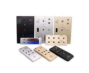
Related Products
Aluminum(Anodized) / Aluminum(Raw finish) / Brass / Plastic / Titanium / CNC Machining Case /
Our Work

Process
News
E-mail:dennis@7-swords.com


 Inquiry


